 |
free plans: how to make a
Plinko |
Basic Description
|
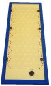
Here is a thoroughly enjoyable project that you can mount on any wall. It's a plinko
display in which you place a thin puck at the top and let go. The puck randomly bounces
its way amongst a series of pins to the bottom where it is held in place by some hidden
magnets. While it may look simple, it takes patience and requires some precise work. We made ours
to be 5' (1.5m) tall. We
think that you will love making and playing with this project! |
Next we need to layout the peg locations. This is more complicated that it may seem
at first. Basically we are going to create a grid on the plywood and use the intersections as
the peg locations. There are other seemingly more elegant and theoretically accurate methods of marking these locations
(i.e. using a compass or a jig) but in practice, these are susceptible to cumulative errors and this is dangerous.
step 3a
With the plywood panel on your worksurface, lets begin the marking process.
We will be making a 2" (50mm) wide frame that will
will encroach onto the plywood area 1" (25mm) from all sides (a narrow strip of pine will be put on the
underside of the pine that overhangs the plywood panel to hide the edge of the plywood). Make a line
demarcating
the area that the frame will take - in our case, this left a rectangle 19" x 58" (48 x 145cm)
|
 |
step 3b
Now you need to decide how many columns you want to have in your plinko display. The rows
of pegs are staggered so the number of columns increases and then decreases as you
move down the display. We chose to make our model 6 columns wide which means that every other row is
one less or 5 columns wide. (Note that if you choose an odd number of columns, the number
of columns does not alternate, it remains consistent). The number of columns you select is not too critical but we would recommend
a minimum of about 4. Increasing the number is fine, but each additional column you make increases
the number of pegs which adds more time to the construction. We were very satisfied with 6 columns and
don't see a need for more. Keep in mind that if you choose an odd number of columns, the sides will not
be symmetrical and the exit pegs at the bottom of the display will not be centered. For this reason
we recommend using an even number of columns such as 4, 6 or 8. As you proceed, consider that
a display with 6 columns requires 7 pegs across.
|
 |
step 3c
This is just an informational step to prepare you for the upcoming steps.
In addition to the field pegs that make up the plinko display, you also need to
include some pegs along the border to prevent the puck from getting caught along the frame.
You could make
the required scalloped shape by cutting into the pine frame, but we like the look achieved with
the use of pegs. Note that we included extra side pegs that are not necessary; see the graphic on
the right for an additional possibility. |
 |
step 3d
If you position the border pegs too close to the frame, they become difficult to paint
when we reach the painting step, so we are positioning them 1/2" (15mm) within the inside
of the frame. We made a mark along both sides; note that these marks are going to be the
centerlines of the pegs. Next measure the distance you have between these centerlines and divide
it by the number (we recommend using an even number) of columns you plan to have. We had 18" (45cm) which
is perfect for the distance between peg centers to be 3" (75mm). Measure and make lines with a straight edge
for these centerline distances along the entire length of the plywood panel. Now repeat this step
by creating vertical lines at the halfway points between the existing vertical lines - these will
be used for every other row of pegs. If possible, use an alternative colored pencil.
|
 |
step 3e
Now we can start to make the horizontal lines. The location of the top and
bottom row of pegs is not too critical, we just want to make sure that there will be enough room
to insert the puck at the top of the display and remove it at the bottom. We used the center
distance between pegs, 3" (75mm) in our case, and added 1" (25mm) and marked our top line this far
from the inside edge of the frame. To prevent confusion we didn't make a complete line, but rather made
hash marks at every other vertical line
|
 |
step 3f
To mark the second and subsequent rows, use a compass and set it at your center distance. Draw an
arc from two adjoining intersections - the intersection of those two arcs will be the location
for your next horizontal line. Using either a large square or by measuring from the edge of the
plywood, draw a hashed horizontal line to complete this row. Repeat this process down the plywood
panel until you reach the bottom. You will need to leave at least the dimension that
you left at the top of the display for the bottom; we omitted a row at the bottom to ensure that
there would be plenty of room for the puck to exit.
|
 |
step 3g
The final marking step is to mark the pegs for the border. We used a composite make
large arcs along the both edges of the display. Then we reset the compass to 1/3 the distance
between peg centers and made short hash marks to complete the peg locations. See the graphic on the
right. We put two border pegs between each row but one would also suffice.
step 3h
The final step in the location marking process is to check the work you have just
completed. A good idea is to make a small circle at each intersection that a peg will be located and
then check that you have the accurate dimension between all of those intersections. In our
case we set our ccompassat 3" (75mm) and verified the spaces between intersections. If you
are off by a small amount, there probably won't be a drastic effect, but if one of the spaces is
too narrow, the puck may get caught and that would be unfortunate.
|
 |